-
BMW E46 Common Coilover Spring Rates
Recently, I was trying to figure out: What spring rate should I be running on my E46?
To be specific, I’ve been looking for a good coilover spring rate for drifting. My car is completely stock power-wise, and my local drifting track is quite tight, low-speed, and technical – an ex-go-kart track.
Previously, I had been running Feal’s 441+ Drift Setup – a 10k front, and 9k rear spring. But this allowed for way too much grip in the rear! I decided to investigate: Was this just a skill issue, or should I be running a stiffer rear spring due to the tight track and low horsepower levels?
To help figure this out, I rounded up data on all of the most popular E46 coilover spring rates – that way I could get a better idea of what each company sells and what rates they’re using!
Coilover Name Front Spring Rate Rear Spring Rate Feal 441+ Drift Setup 10k 9k Feal 441 Non-Drift 8k 9k Megan Euro Street 7k 8k BC Racing ER Series 8k 12k BC Racing BR Series 8k 10k ISC N1 10k 12k Ohlins Road and Track 6.1k 7.1k Fortune Auto 500 8k 10k Stance XR1 9k 10k HSD Dualtech 7k 7k HSD Dualtech Track 12k 14k Tien Street Adance Z 7k 8k And finally, a few random recommendations I received:
Setup Name Front Spring Rate Rear Spring Rate Drift BCs 10k 14k Chelsea Denofa 10k 12k Feal’s staff shop car 12k 12k If you’re curious, in the end I decided modify my existing Feal’s 441+ setup, keeping a 10k Swift spring in the front and moving up to a 14k in the rear. I also picked up a pair of 12k Swift springs at the same time, that way I can swap them out in the future or try out different setups if the 14k’s end up being too much.
Anyways, that’s all I’ve got for ya! A short and sweet article, just so someone else can hopefully make use of the research I’ve already done. Enjoy!
-
What’s Inside: BMW Seat Module (SMFA)

Today, we’re tearing down a 2019 BMW 440i Seat Module – called an “SMFA” by BMW (Which stands for “Sitzmodul Fahrerseite”, or “Seat Module Driver’s Side” in German)
What is it??

In the vehicle, this module lives under the car’s driver seat. It is responsible for controlling the various seat adjustment motors, as well as heated or cooled seat functionality. Each motor within the seat has a hall effect sensor attached, allowing this module to know the absolute limits of each adjustment and detect when faults in seat adjustment occur.
A roughly-estimated block diagram of this module is as follows:

Why tear it apart?
The high amount of connectivity the module has makes it somewhat interesting to reverse engineer – it can store faults, trigger seat motors, and converse via the vehicle’s CAN bus!
Additionally, seats are one of the first items which are replaced when turning a vehicle into a race car – this module is a perfect example of something that could throw fault codes or cause other headaches when removed from a race car. If we’re able to reverse engineer and understand this module better, perhaps it could allow others to build a replacement control unit which is able to silence any fault codes or errors when using an aftermarket bucket seat in the car! (Note: If you’re modifying safety devices in a vehicle such as seats, airbags, or steering wheels, always be sure to consult a professional and follow all relevant traffic laws when making modifications. This blog post is not professional advice!)
Outside the Module
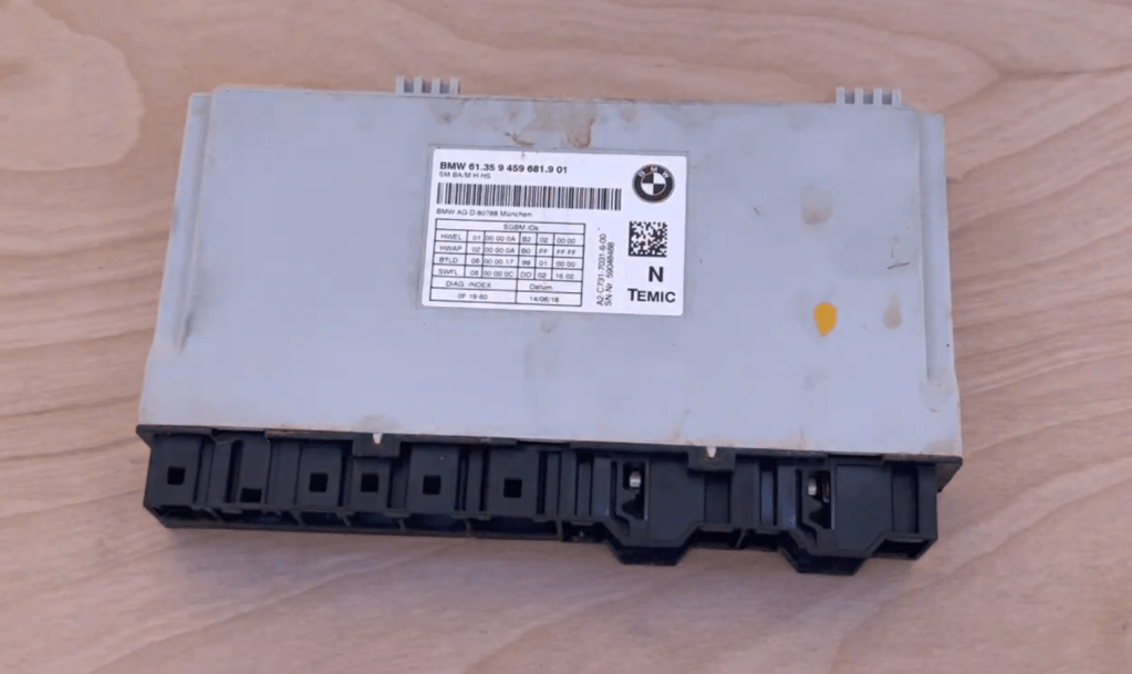
This here is the module we’re playing with – somewhat water damaged, it was removed from my car due to the previous owner spilling some unknown liquid under the driver’s seat. Did they drop a pop? Leave a window rolled down? Who knows!
Despite this, when the module was removed from the vehicle, it was working well – the harness it was connected to had a short, but the module was still able to store faults, trigger seat motors, etc.
For those following along at home, the part number of the module we’ll be disassembling today is 61.35 9 459 681.9 01.
Inside the Module
To start with, let’s pop the module open and take a look at the PCB inside. With no visible fasteners on the module, this means we’re cracking it open with a screwdriver!
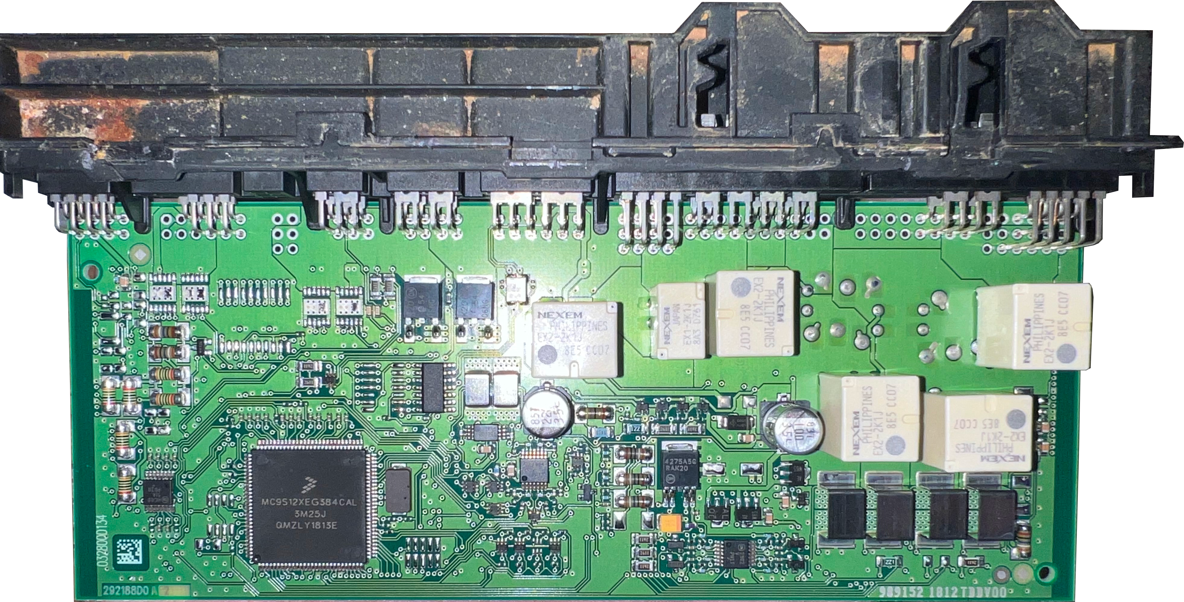
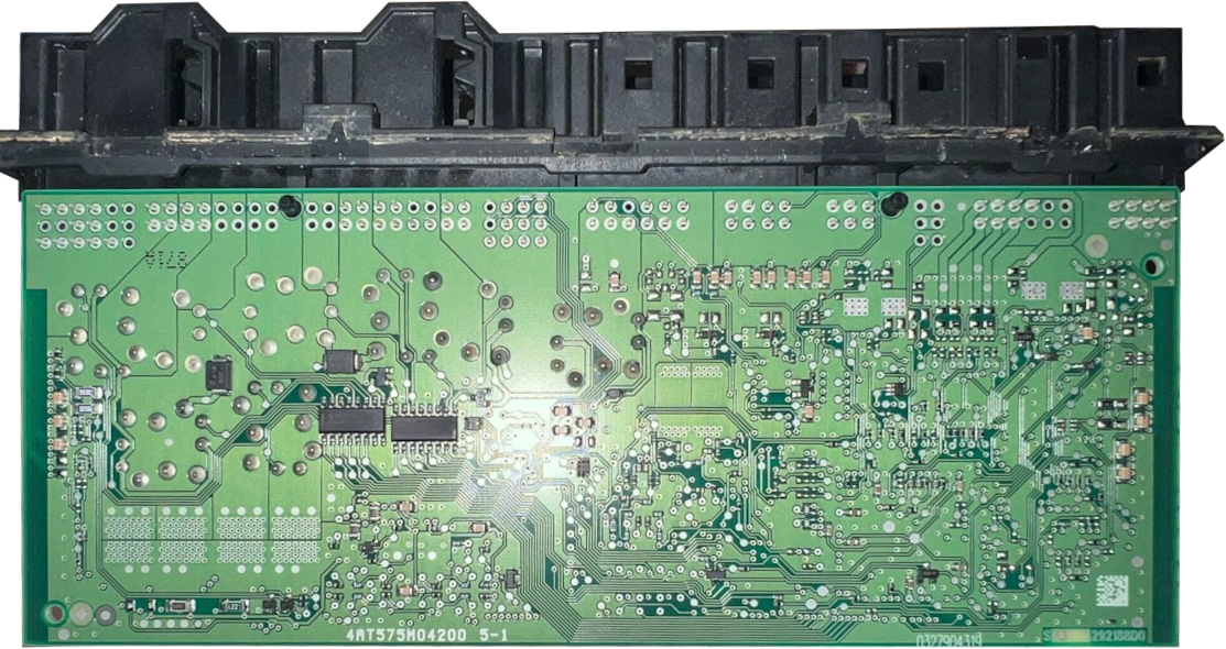
Ah yes, a nice and surprisingly-clean PCB (given the state of the exterior). Lets dive in!
PCB Component Analysis
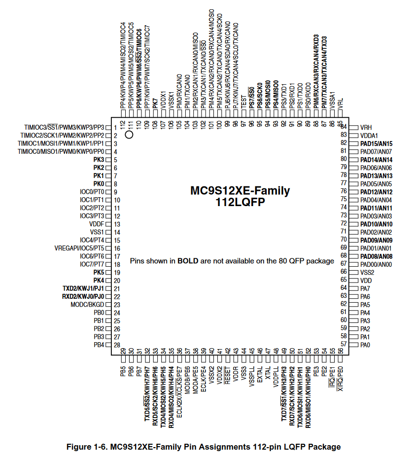
The main processor of the module is an NXP/Freescale MC9S12XEG384CAL – the datasheet of this process can be found here. This microcontroller supports a number of interesting technologies – I2C, SPI, DBG, 5 separate MSCAN transceivers, PWM output, and more! Due to the MCU’s LQFP physical chip packaging (this MCU uses the 112-pin variant, for those who are curious), this processor should also be extremely easy to attach test probes to. This will allow for the interception of various messages and serial communications transmitted to or from the chip. I’ve attached a photo of the MCU’s pin-out extracted from the datasheet below.
As for the rest of the PCB, we have a number of Nexem EX2-series automotive relays (datasheet here), ON Semiconductor voltage regulators (datasheet here) and multiplexers (datasheet here), and a few other miscellaneous odds and ends.
Overall, a surprisingly basic PCB!
Future Reverse Engineering Work
With the exposed nature of the MCU’s LQFP packaging, I think it would be interesting to attach a signal analyzer to the processor to log and interact with a few different interfaces. In particular, analyzing all of the CAN traffic sent to and from the module during normal operation could show how certain features like seat adjustment motors, heating, or fault code reading could be triggered remotely via the CAN bus.
Keep an eye out for future blog posts diving deeper into this module!
Additional Information
For those playing along at home, I figured it may be useful to include a full transcript of the information from this module’s label. Hopefully this helps someone fix an issue with their own module!
BMW 61.35 9 459 681.9 01
SM BA/M-H-HS
A2-C731-7031-6-00
SN-Nr. [redacted]SGBM-IDs HWEL 01 00 00 0A B2 02 00 00 HWAP 02 00 00 0A B0 FF FF FF BTLD 06 00 00 17 99 01 00 00 SWFL 08 00 00 0C DD 02 16 02 DIAG.-INDEX Datum 0F 19 60 14/06/18 -
Honda Civic EP3 – 2D Aerodynamics
Lets talk aerodynamics!
Overview
I’m relatively new to automotive aerodynamics, with only a rudimentary understanding of aerodynamic concepts. My goal is to start my journey down this rabbit hole with my very own pride and joy, my 260,000-mile EP3 Civic!
The overall goal is to modify the car in a way that is based on improving track times, research, and hard data. Not just purchasing off-the-shelf parts, but rather marking and measuring improvements, why they occur, and where you could develop them in the future.
To begin, I wanted to learn the most basic piece of aerodynamic analysis: a two-dimensional air flow simulation!
Through reading the first few results on Google for Computational Fluid Dynamics (CFD) simulation software, I quickly learned that it would require something which I do not possess: money! My next path forward was to research CFD software which does not require money!
This research landed me on the home page of the wonderful software Flowsquare+.
The Software
Flowsquare+! This software kicks butt, and its free! (You can read more about it or download it here)
I first discovered this through FULL TILT POTATO‘s video “Honda CRX Aero Modeling”. The video shows off a relatively simple 2D CFD simulation that seemed to present everything I was looking to learn: the basic aerodynamics of a car’s 2D shape!
In the description, he linked to the original version of Flowsquare, which brought me to learning about Flowsquare+, the latest revision of the software!
It’s a relatively simple suite of tools for performing both 2D and 3D CFD. Per their own website:
Flowsquare+ is a two- and three-dimensional computational fluid dynamics (CFD) software, which has a very handy and intuitive user interface which allows more users to perform their own simulations without too much cost and effort.
https://fsp.norasci.com/en/index.htmlAnd best of all, the software is free!
Setting Up the Simulation
Lucky for us, one of the Flowsquare+ Tutorials entitled “Flow Around a Car (2D)” explains the process of importing a BMP of a car’s outline, setting up a 2D flow simulation within Flowsquare+, and exporting the results!
Before we continue, I highly recommend walking through the linked tutorial above.
To modify the tutorial simulation to fit the EP3 Civic, all we need to do is modify the car’s outline from a Mazda RX7 to the outline of an EP3 Civic!

The default Mazda RX7 ‘bcXY0.bmp’ image. We’re going to go through a few steps to add our own outline:
- Determine the size of the stage – this will help us size our vehicle to be realistic within the simulation!
- Find the size of the vehicle we’re creating an outline of
- Find a quality side-profile view of the vehicle we’d like to create an outline of
- Convert the photo into a black-and-white bitmap outline!
We’ll start with the first – stage sizing.
Stage Sizing
The hardest part about adding in our own vehicle outline is getting the sizing correct! To ensure we’re accurately sizing the outline, we’re going to need a few variables from the tutorial:
- 512×256 – The resolution of the bcXY0.bmp image
- lx – 9m – This is the length of the ‘stage’ in the X-direction
- ly – 4.5m – This is the length of the ‘stage’ in the Y-direction
Using this information, we can determine that 512px (the width of the stage) is equal to 9m in length. That means each meter is approximately 56.88px in length! This measurement will be handy in future steps for converting our car to the right size bitmap outline.
Finding the Vehicle’s Size
This step is relatively easy – you just need to Google it! Websites like Encycarpedia offer a number of stats about every vehicle under the sun, including the dimensions. While aftermarket modifications such as wings, bumpers, or body kits may change the overall measurements, the factory-standard measurements can be a great starting place to begin creating a model of your vehicle.
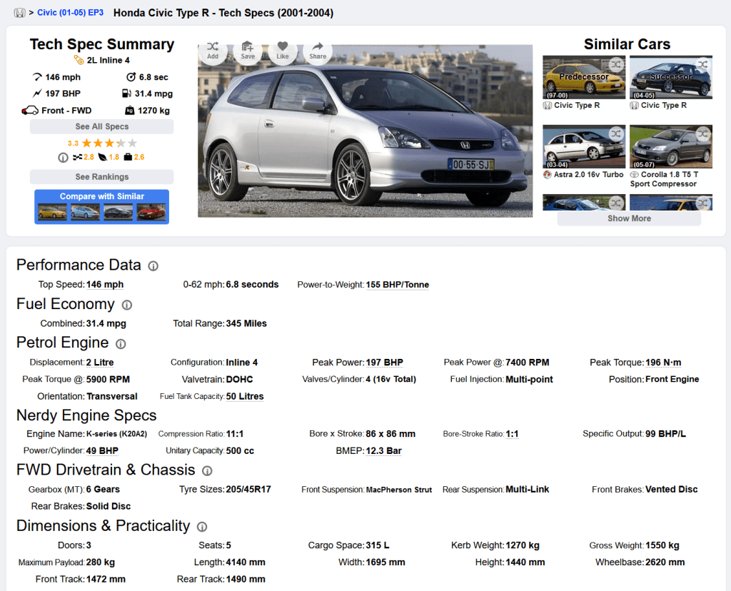
The Encycarpedia entry for the 2001-2004 Honda Civic Type R According to Encycarpedia, the overall length of a 2001-2004 Honda Civic Type-R is 4140mm. Exactly the information we need to know for our simulation!
If you would prefer a more official source than Google, or if websites like Encycarpedia are unavailable to you, information on your vehicle’s dimensions can also commonly be found in the owner’s manual.
Locating a Side Profile Photo
The next step is to find a photograph with a perfect side profile of the car. This is unfortunately harder than it sounds – even slight shifts in perspective can make the side profile extremely inaccurate, so taking some time to find the perfect photo is well worth the effort spent.
For this step, I simply searched “EP3 side shot photo” on Google Images:
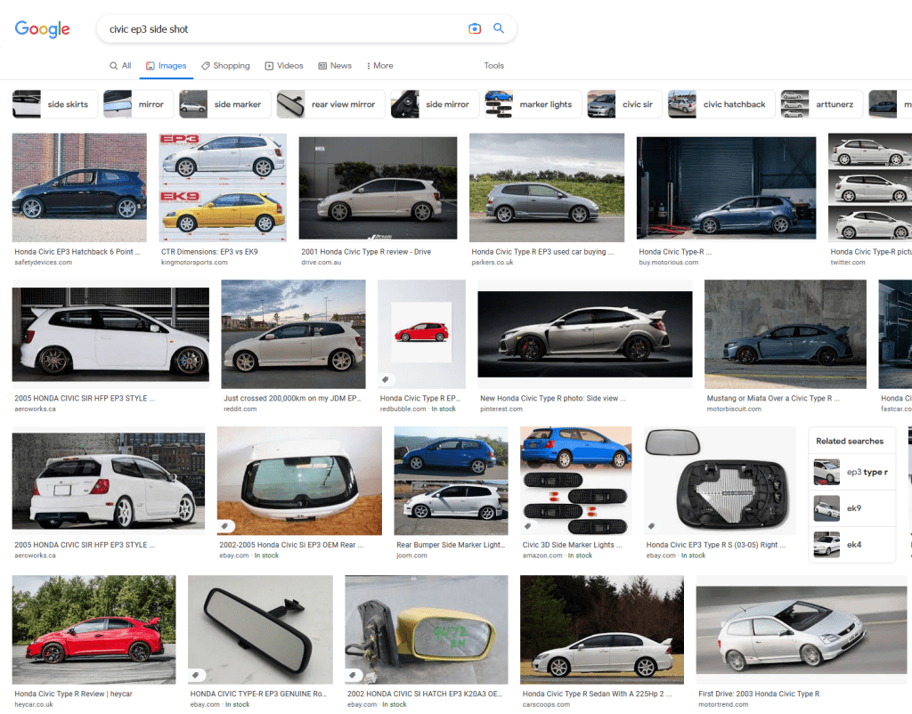
Many high quality results, many low quality results… In the end, I settled on the below image:
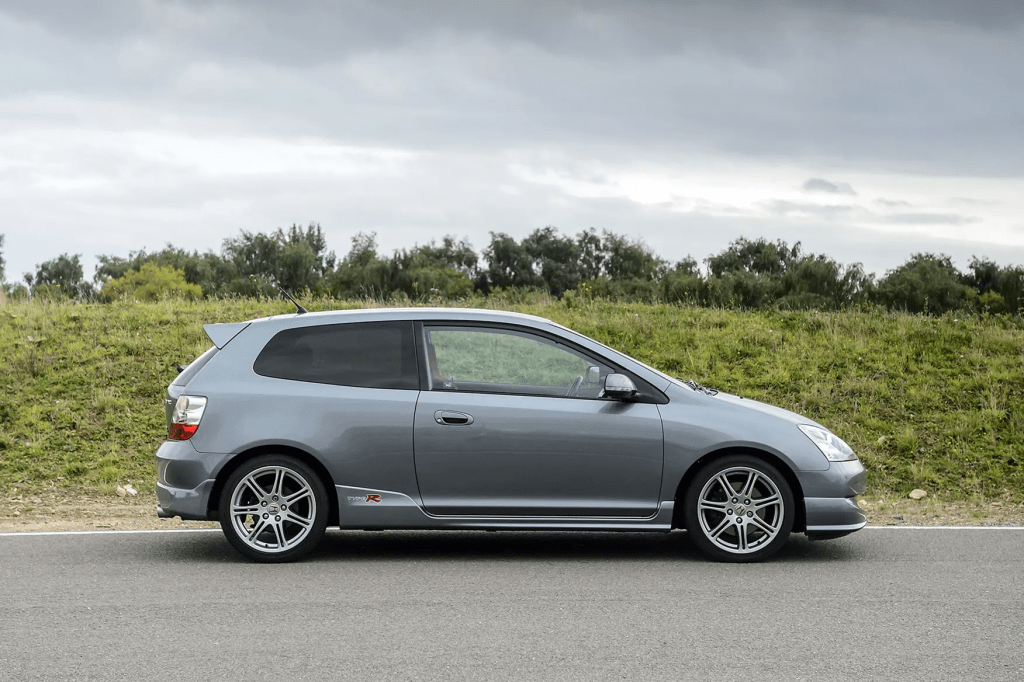
Source: FastCar.co.uk The professional course of action here would most likely be utilizing the 2D image generated by a proper 3D CAD model or 3D scan of a vehicle, however I don’t have access to that! For our purposes, reverse engineering the side profile using a photograph will be fine.
Converting the Photo into an Outline!
Now, we’re going to get into some cursed Photoshop wizardry (well, I’m actually going to be using GIMP, because I don’t have a Photoshop license).
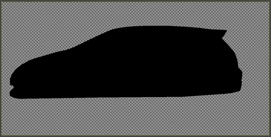
The first part will be cutting out the car’s outline. For this, I used GIMP’s Free Select tool to trace the outline of the vehicle, leaving me with this!
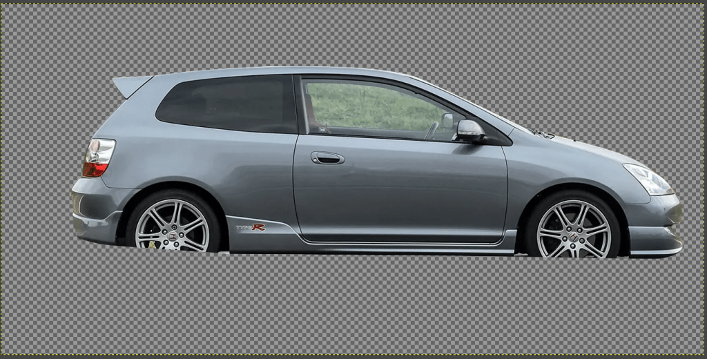
From here, we’ll flip it horizontally in order to mirror the direction of the demo outline (Image -> Transform -> Flip Horizontally), and work on filling it in completely with black.
To do this, we’ll use the Fuzzy Select tool to select the now-empty area around the car, and then click Select -> Invert in order to invert our selection, so that only the car’s outline is selected again!
From here, create a new layer, hide the layer with the actual car’s image, and use the paint bucket tool to fill the selection area in with black.
Huzzah, we have an outline! Now is where the hacky part comes into play…
With the outline’s selection still active, click on the Scale Tool and click on the outline – a box showing the outline’s current dimensions will pop up, as seen below:
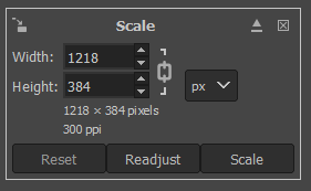
This is where we’ll be manipulating our images size! Remember those values we researched earlier? This is where those come into play.
From our research, we discovered the EP3 Civic should be 4140mm in length. Additionally, in the 512×256 resolution that the simulation uses, 1m = 56.88px. So, to extrapolate:
4140mm == 4.14m. If 1m = 56.88px, our vehicle’s pixel size should be 4.14 * 56.88px, which equals 235.4832px. We’ll round this to 236px to make things somewhat easier in GIMP.
So, with a total length of 236px, it’s time to resize our image! In the scale box, ensure that the width and height values are locked to stay in ratio to each other (the ‘chain’ symbol between the two numbers), and enter 236px for the width.
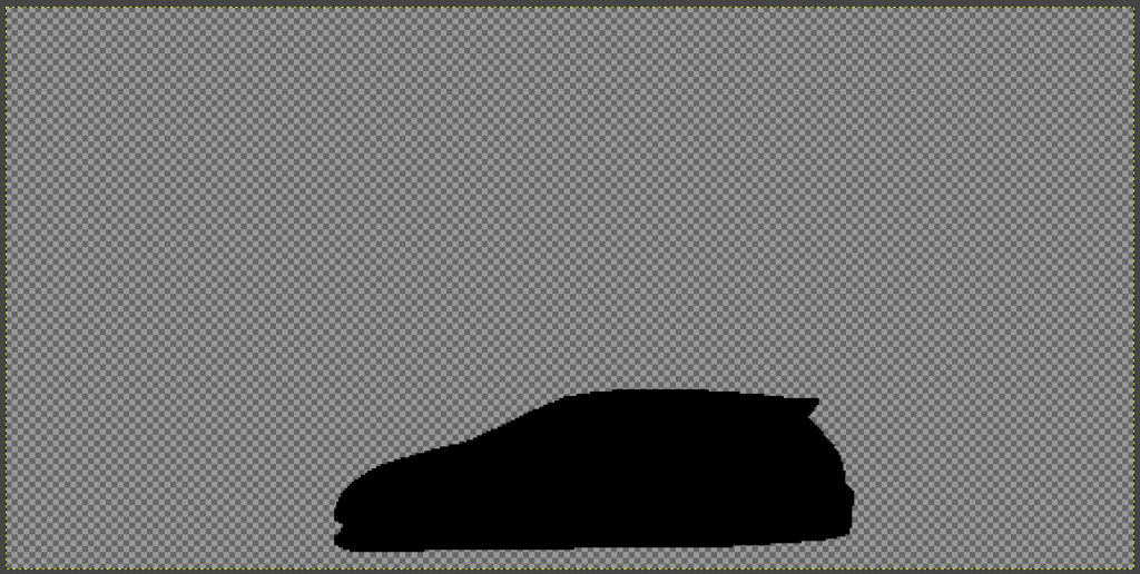
Congrats, our outline is now properly sized for the stage! Now is also a good time to resize your overall canvas to 512×256, if you haven’t yet.
From here, the final step is to create the overall background and boundaries that Flowsquare+ recognizes. The background is easy – simply create a new layer and paint bucket the entire thing white!
As for the boundaries, I created mine to be exactly 3px wide, which seemed to work well. The easiest way to do this is to create a new layer, select the entire canvas (Ctrl+A), and then click Select -> Shrink… -> 3px, and then Select -> Invert. Now, use the paint bucket to fill this new selection area with pure blue! (Hex Code: 0000ff) Finally, you’ll have to delete the furthest right side of the border in order to give the air somewhere to exit. I did this by selecting it free-hand with the rectangle select tool and hitting Delete.
Once you’re all said and done, it should look something like this!

The image above is actually my properly-sized EP3 .bmp image – feel free to download it if you’d like to use it in your own simulations!
Bringing it All Into Flowsquare+
The final step before we run our simulation is to actually bring our new outline bitmap into Flowsquare+!
Doing this is as simple as swapping out the image file in the RX7-based tutorial, while maintaining the values of each of the variables that are set.
First, rename your new vehicle outline to match the title of the RX7 outline – ‘bcXY0.bmp’. Next, back up the RX7 outline (optional) and copy your new outline in its place!
Then, simply open Flowsquare+ and open the project, by selecting the associated project param.txt file.
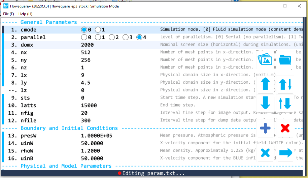
The Flowsquare+ Options I Used Above are the default tutorial simulation variable settings, and they’re what I used for this sim! The only options I would recommend changing are in relation to the simulation length and image saving options – I modified the ‘latts’ variable to equal 15,000 (the total number of steps), and ‘nfig’ to equal 20 – the interval at which screenshots should be taken. This isn’t necessary unless you’re looking to render a video of your results!
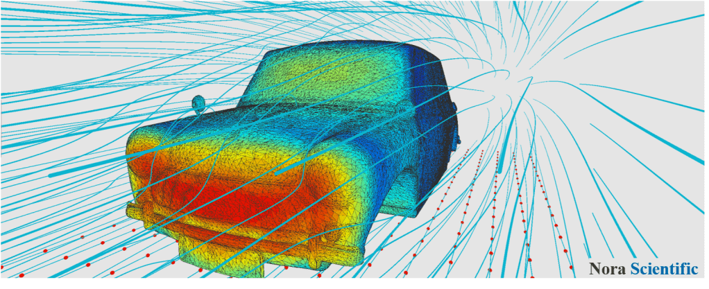
I render my videos at 60fps, so 20 steps per frame @ 60fps == 1200 steps per second overall. Why this speed? Well, mainly because it’s the speed at which the Nora Scientific demonstration video was rendered at on YouTube – I just copied them.
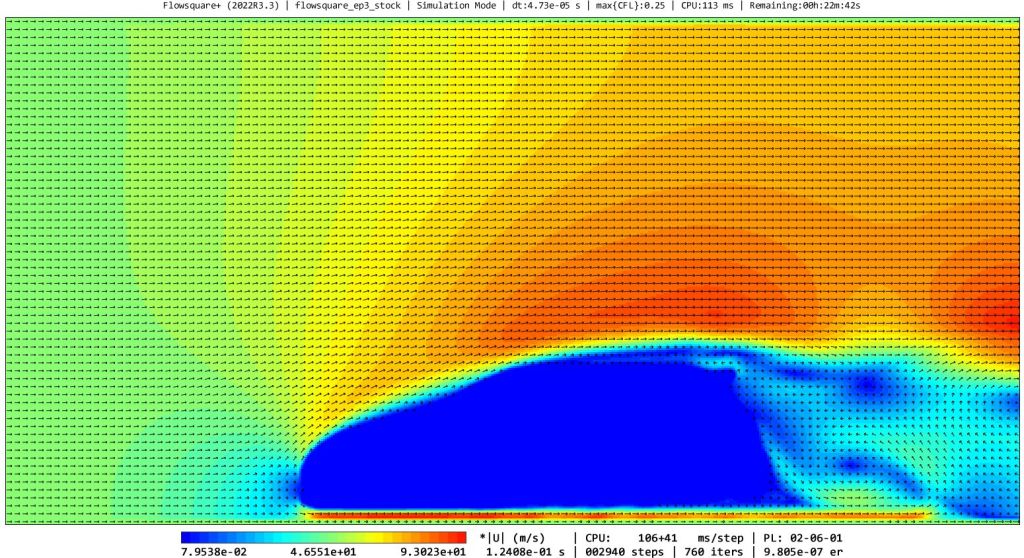
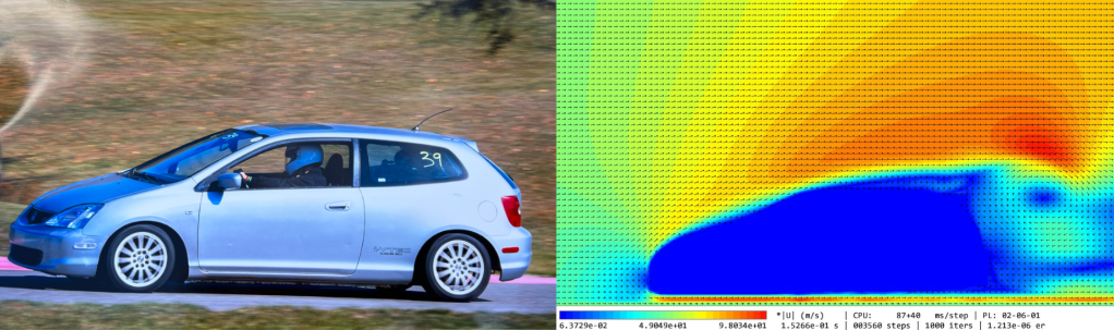
The Final Product!
Below is my actual rendered EP3 Civic simulation.
And with that, we’re done!! I’m sure there’s a ton to expand on and learn from – ways to improve the simulation, ways to simulate spoilers, wings, and different air speeds, and you could probably write a whole bible on how to interpret the results.
But that’s not what we’re here for – today, we got a basic sim working! In future blog posts we’ll dive further into the data, an analysis of it, and where to proceed from here.
Thanks for reading! If you have any feedback or comments, feel free to leave them below or reach out.
-
Hello, World
This is my first post. Welcome to my blog!
